4. lpGBT and VTRx+
The VLDB+ houses one lpGBT and one VTRx+ connector in the upper middle side of the board.
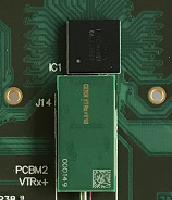
Fig. 4.1 VLDB+ lpGBT and VTRx+
4.1. lpGBT
Almost the 100% of the lpGBT signals are made available on the VLDB+ through different interfaces such as VTRx+ connector, FMC HPC connectors, SMA connectors, simple pin connectors, testpoints, bullseye connectors and more. The availability of the lpGBT’s features on the VLDB+ are listed in the Section 13.
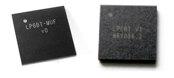
Fig. 4.2 lpGBT V0 (left) and lpGBT V1 (right)
The VLDB+ V2 is lpGBT V1 compatible. That means that some VLDB+ V2 houses an lpGBT V1 instead of V0. Moreover, if an lpGBT V0 is housed on your VLDB+ V2, you have the option of desolder it and solder an lpGBT V1.
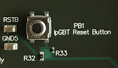
Fig. 4.3 lpGBT reset button.
Note
To reset the lpGBT you have to press the push button PB1. In the VLDB+ V1 (not the V2), as soon as the PiGBT Control Toolkit is connected to the VLDB+,
pressing the PB1 will have no effect and its control is done through the PiGBT (reset button on the PiGBT web interface).
4.2. VTRx+
We can provide the VTRx+ module together with the VLDB+ (on request). The VTRx+ connector is the J14.
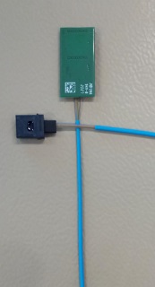
Fig. 4.4 VTRx+ V10
Please note that only one Tx link is connected to the VTRx+ for simplicity reasons (refer to the Section 13.10).
The VTRx+ MT connector has 12 optical lines where only 2 (1 RX and 1 TX) are used to communicate with the lpGBT housed on the VLDB+. The following picture describes the VTRx+ MT connector:
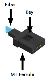
Fig. 4.5 MT connector of the VTRx+
The pre-production VTRx+ which we can provide together with the VLDB+ Kit, uses the lines 6 (VTRx+ TX) and 7 (VTRx+ RX) to transmit and receive data in case the MPO Fanout goes from channels 1 to 12.
To connect the VTRx+ MT connector to an MPO connector, you have to put the guide pins inside the MPO connector. Then, take a look at the keys from the MPO and MT connectors, both must be in opposite directions. The following picture shows the correct connection using both connectors.
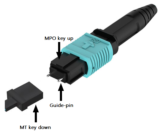
Fig. 4.6 Correct MT-MPO connection
Warning
The J14 connector has not a high durability. Please, avoid to connect and disconnect the VTRx+ repeatedly
in order to preserve its durability.
4.2.1. Back-end MPO Fanout Patchcord
We do not provide the neccesary MPO Fanout Patchcord and the two MPO guide pins to interconnect the Evalution Kit FPGA transceiver and the VTRx+. However, at CERN you can request these tools opening a ticket here. Fill the .csv that they provide with the following:
Type Number Type Cnn. A Assembly Type de cord Cnn. B L More info. Patch cable 12 Multimode 50/125 OM4 12-Fibres MTP/MPO (male) A (standard) 1 Fibre (Simplex) LC/PC 1 m 12 fiber fanout MTP to LC
The guide pins will be provided with the MPO connector.